Context
I am refinishing a lathe, and as part of that refurbishment, I’m bringing some shafts to the correct size for a bearing seat. Unfortunately, it is rather difficult to accurately remove 20 microns from a shaft when your lathe is in a hundred pieces on the floor. :(
Fortunately, 20 microns isn’t much and can easily be removed by abrasive means. However, this requires a lap, which are historically made of cast iron, owing to its low cost, good geometrical stability, and porous structure. In particular, grey cast iron contains many small pockets of graphite that the abrasive media easily embeds into. (Citation: Stahli) Stahli, A. (n.d.). The Technique of Lapping. Retrieved from https://www.stahliusa.com/stahli-publication/the-technique-of-lapping/

However, I don’t have much cast iron (and none of known grade) and machining a lap out of aluminum on my mill seemed like a waste of time and material.
Instead, I figured I could print one!
Part Design
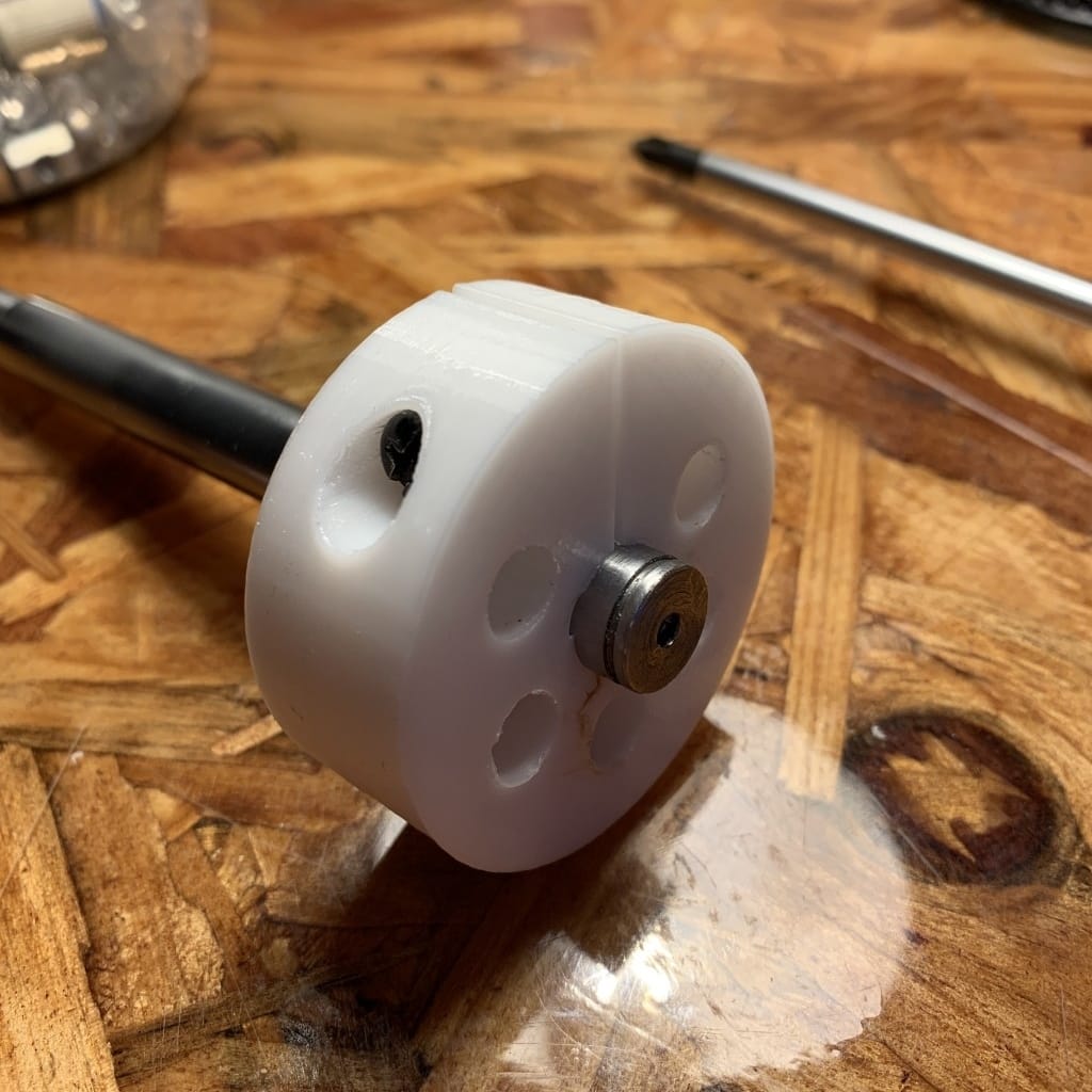
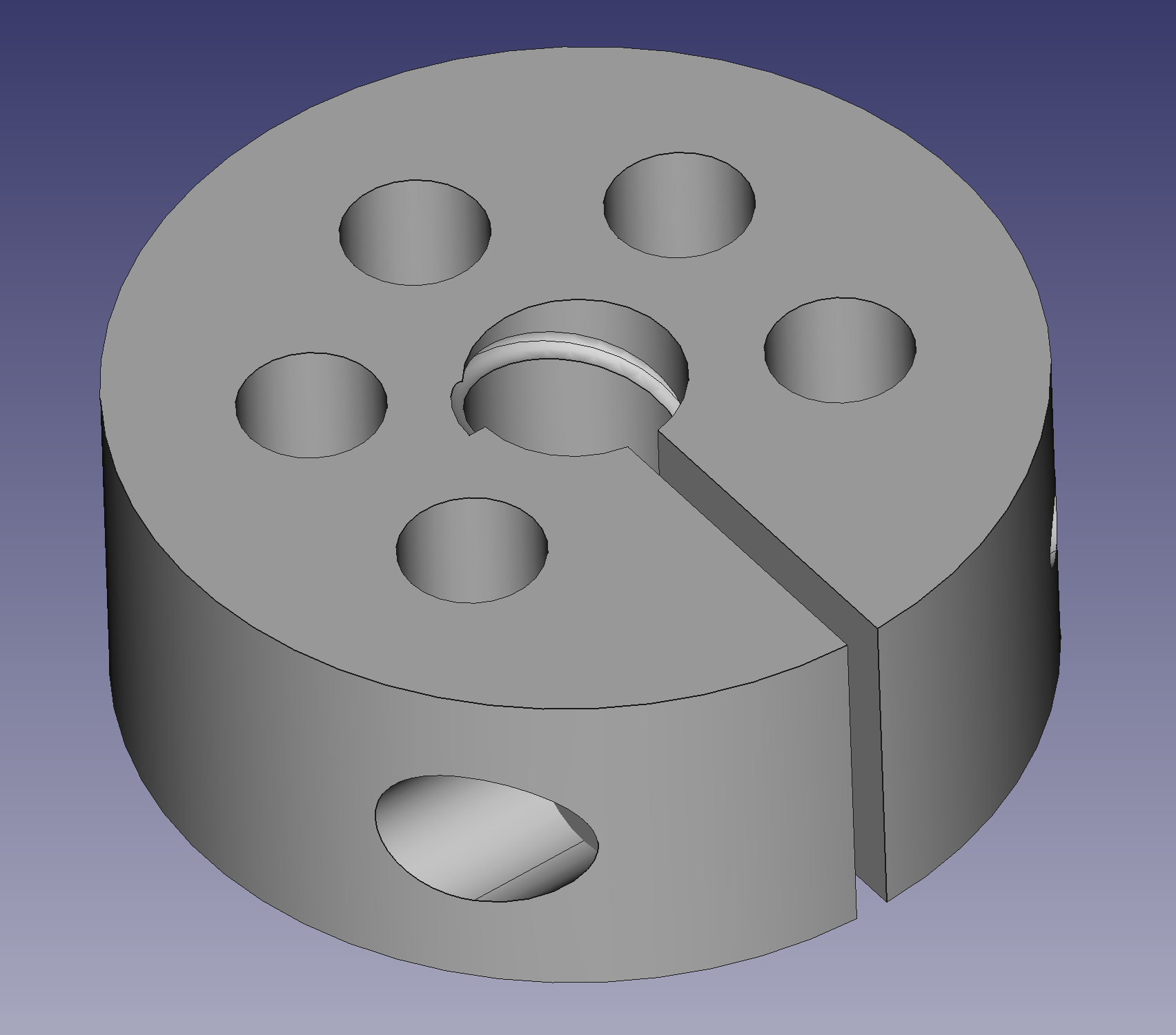
I designed my PETG part around several designs I saw from American Lap, Helical, and Stähli. It’s quite simple, really – a 12mm reamed hole forms the main cutting surface, and equispaced holes around the lap allow it to close evenly from a slit on the side. A M5 tap is used to form threads, and a M5 bolt controls the lap pressure.
I’m sure I could attempt to model and optimize the hole placements, but I have not yet found it necessary. Perhaps in the future I will have good enough process control and metrological instrumentation to accurately test lap shape.
A FreeCAD render, which can be downloaded here. This particular lap had a nominal inner diameter of 12mm.
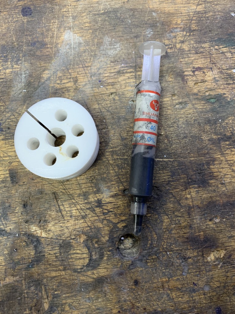
I used 40 (400 grit) micron diamond paste. The paste seemed to work, but was the absolute cheapest paste I could buy. The brand is Shuangxin, and was purchased from Aliexpress for less than a dollar. I suspect it’s a bit light on diamonds, and will experiment with using silicon carbide, alumina, and by own diamond/grease mixes to see if I can improve material removal rates and finish.

Technique
Fundamentally, there are two cutting modes in abrasive machining. The first utilizes abrasive embedded in a matrix – sandpaper, a charged lap, roughing stones, etc. The other mode is free abrasive rolling between two surfaces, abrading both as it degrades. Both are valid ways to remove material, but given my very soft lap, I found superior results by embedding the abrasive.
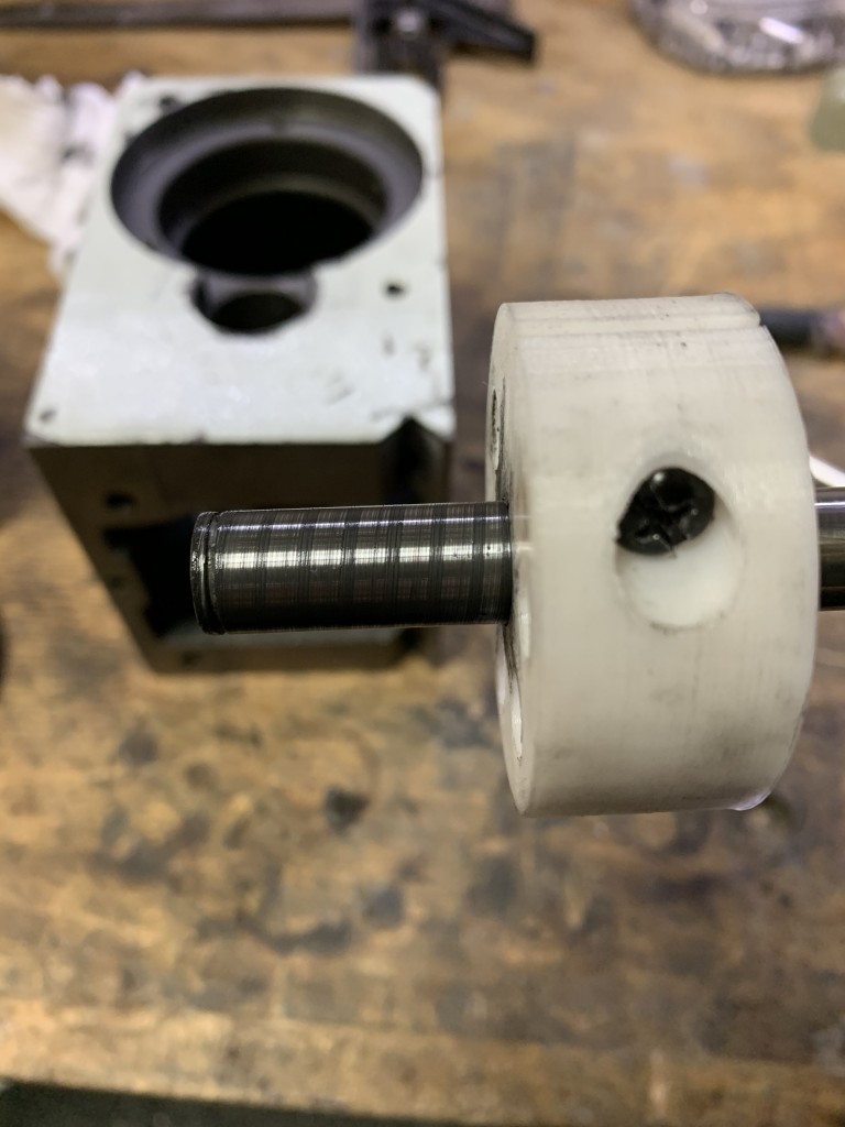
The basic technique is to coat the lap and object in a light coating of lapping compound. I then put the lap on the shaft, and tightened the screw to to fully close the slit – this exerts a tremendous amount of pressure on the shaft and embeds the diamond in the soft plastic. To begin lapping, I backed the screw out as to be only slightly tight, and ran the shaft in a drill at about 250 RPM. I then gently ran the lap back and forth on the shaft, much like a spindle sander.

In using the laps, I found the biggest threat to be heat buildup. Too much friction will quickly deform the lap, and cause it to lose hold of the diamond in the plastic, ruining the material removal rate and dimensions of the lap. As such, I found lower RPMs and pressures to work substantially better than higher RPMs and higher pressure.
I was surprised to find that at the right speed and pressure, it was quite easy to tell the difference in shaft diameter as fine as 10 microns. I estimate I removed approximately 5 microns per minute, although this is a very rough estimate.*
Results
I’m very pleased with the results. I don’t have a profilometer to quantify the results, but the surface is wonderfully smooth. There are visible swirl marks, but that is to be expected with 40 micron paste. A huge benefit of 3D printing laps is the easy with which a set can be assembled, minimizing abrasive contamination between stages.
I was able to hit my target dimension of 12.000mm. This is quite tricky – assuming a CTE of 12E-6, my 12mm steel shaft will increase in diameter by almost 2 microns if I warm it in my hand from a 60F garage.
Apart from the correct OD, I also noticed an improvement in circularity, with the new parts significantly less out of round, by 5 to 10 microns. However, the pre-lapping shaft appears to have been cylindrically ground with a brick, so it’s hard to say if I was actually measuring the shaft and not just a burr.

Resources for further work
The design is heavily inspired by the excellent resources at Helical Lap and American Lap. I also learned quite a bit about lapping more generally from Stähli, which published an excellent “The Technique of Lapping” PDF.
